Kierkegaard
Measurements

Version 0.31 Vertical Responses:

Below are the vertical responses and some further analysis about early reflections from floor and ceiling.
I recorded the vertical responses of three different configurations: MTM, MT and TM in order to show the differences. It is also planned to compare the three versions sonically with instant switching because I want to hear myself if and in how far floor and ceiling bounces influence the timbre of the combined sound and the localization of the phantom image based on a real life example. There are quite intensive studies by Søren Bech [1], [2], [3] but I think it is anyway instructive to quantify the effect myself.

Measurement conditions:
Mic. distance = 0.5m
Mic. reference = tweeter in all cases
Speaker was standing on the floor
FRs ungated

MTM: 0°...60° down

MTM: 0°...60° up

MT: 0°...60° down

MT: 0°...60° up

TM: 0°...60° down

TM: 0°...60° up

The following graphs below analyze the early reflections according to Devantier. The definitions are listed in Toole [4].

Floor bounce: Average of 20°, 30° and 40° down
Ceiling bounce: Average of 40°, 50° and 60° up.

MTM floor bounce

MTM ceiling bounce

MT floor bounce

MT ceiling bounce

TM floor bounce

TM ceiling bounce

The diagram to the left describes the listening window. It is the average of
+-10° vertically, 0° and +-30° horizontally.

Analysis:

The vertical dispersion of the MTM configuration is not quite symmetrical due to the driver placement on the baffle but in total they are more similar to each other than the up and down responses of the MT and TM configurations.

The peak of the tweeter baffle step around 3KHz creates some excess energy but this energy lies in a benign frequency range. It is not assumed to negatively impact the timbre of the sound but it might contribute to frontal localization of the phantom image according to the Blauert bands (compare eq. of Demokrit and Demokrit-T).

[1] Søren Bech, Timbral aspects of reproduced sound in small rooms part I
[2] Søren Bech, Timbral aspects of reproduced sound in small rooms part II
[3] Søren Bech, Spatial aspects of reproduced sound in small rooms
[4] Floyd E. Toole, Sound Reproduction, The Acoustics and Psychoacoustics Of Loudspeakers And Rooms, first edition, 2008, page 387


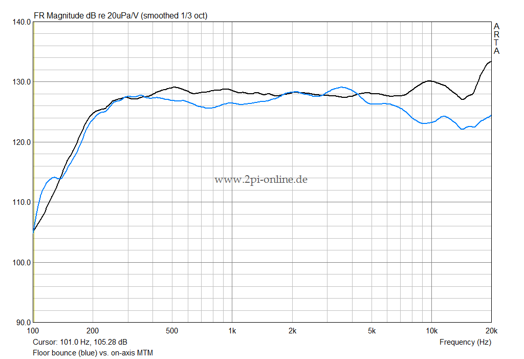
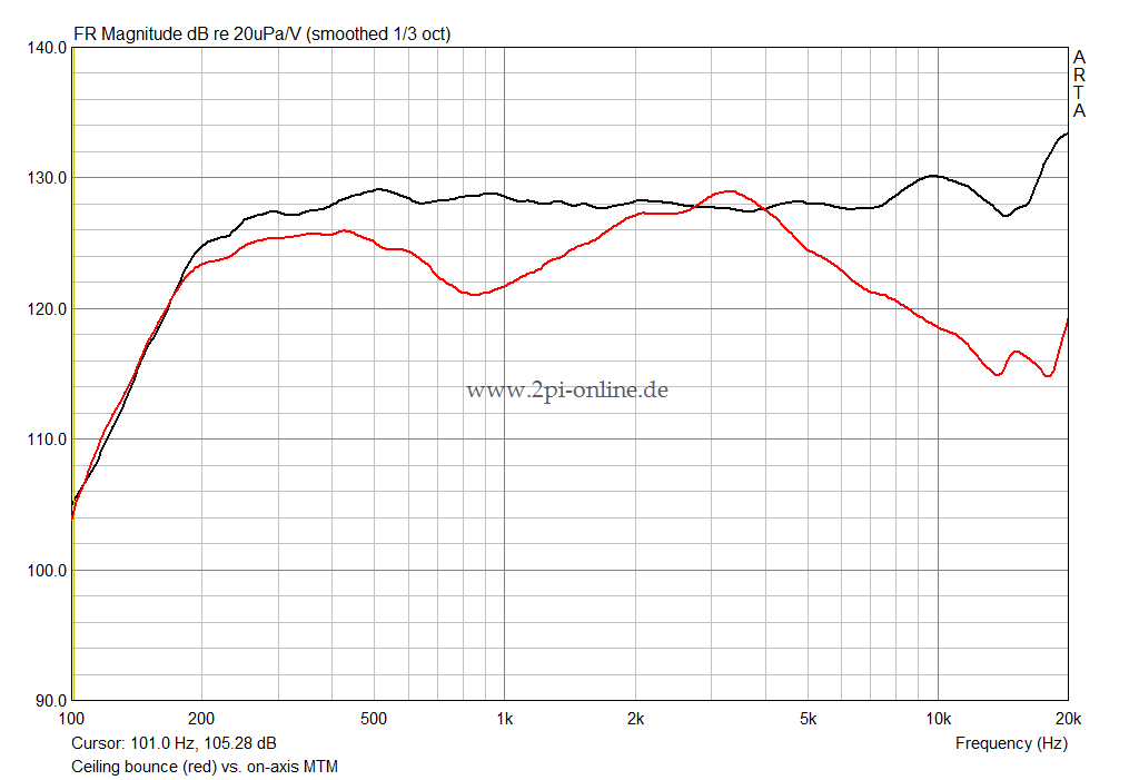
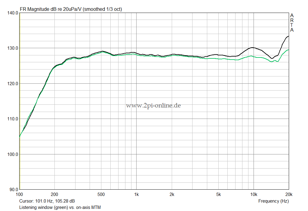
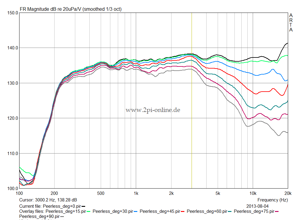
In the test parcours the speaker has to go through during development it was found that the 650 Hz sag and the unevenness of the FR below was not caused by the typical internal resonances alone but by stuffing issues with the housing part of the upper mid wooofer. The cabinet was over-damped and stuffed ineffectiviely.
Also, the stuffing of the lower mid-woofer cabinet was not optimal.

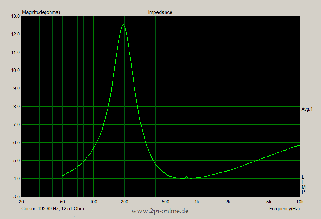
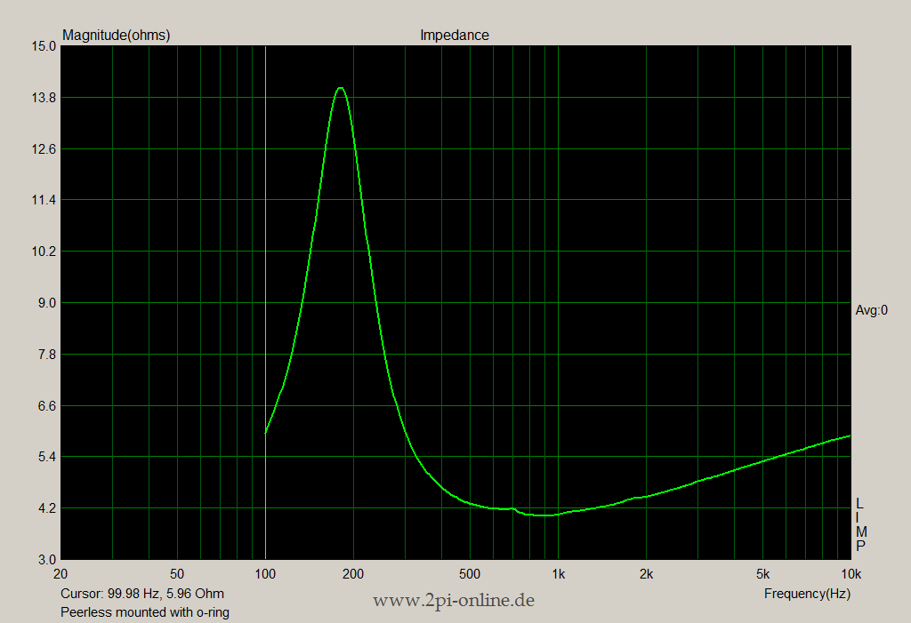
So the issues have been sorted out step by step supported by measurements of the electrical impedance, which nicely reflect resonance issues.
During the course of re-damping, a few re-designs of the housing had been implemented to further support the effectiveness of the damping. Some of which were:

 - shortening the tweeter pipe inlet in order to make the pipe construction more compact and better follow the internal wooden structure of the cabinet

- provide more space around the pipe for damping material where it can be more effective compared to the pressure maxima towards the bottom of the housing.

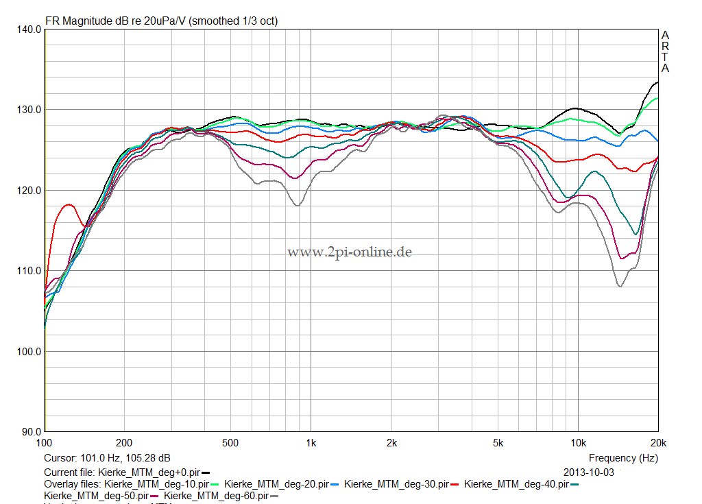
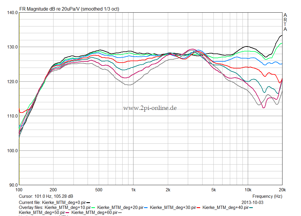
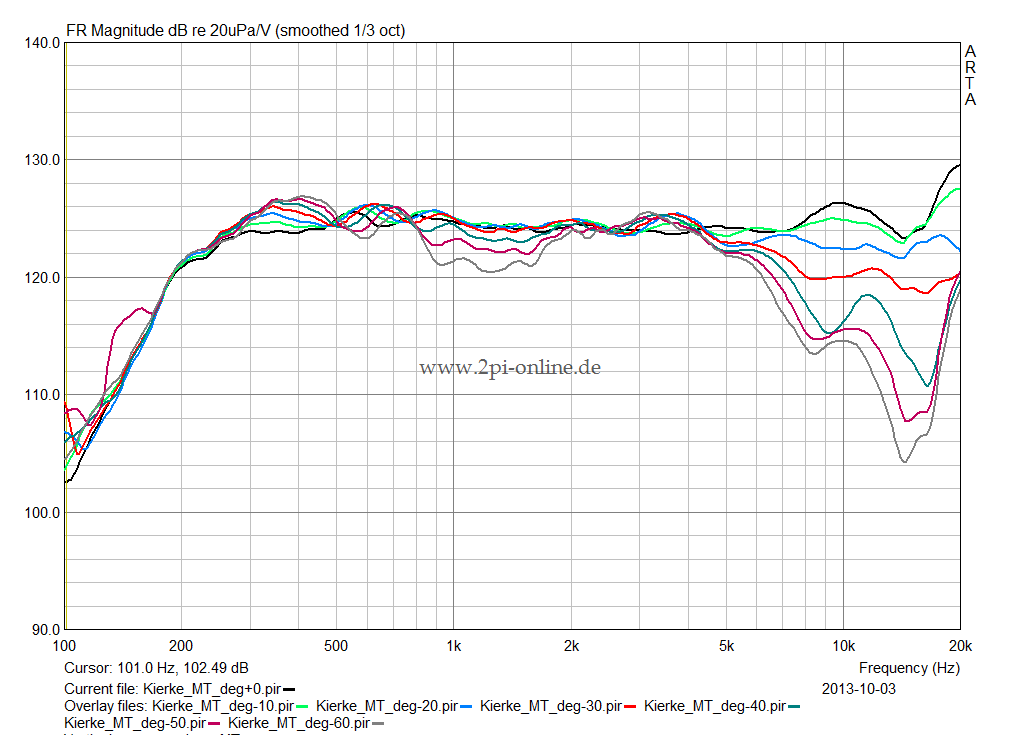
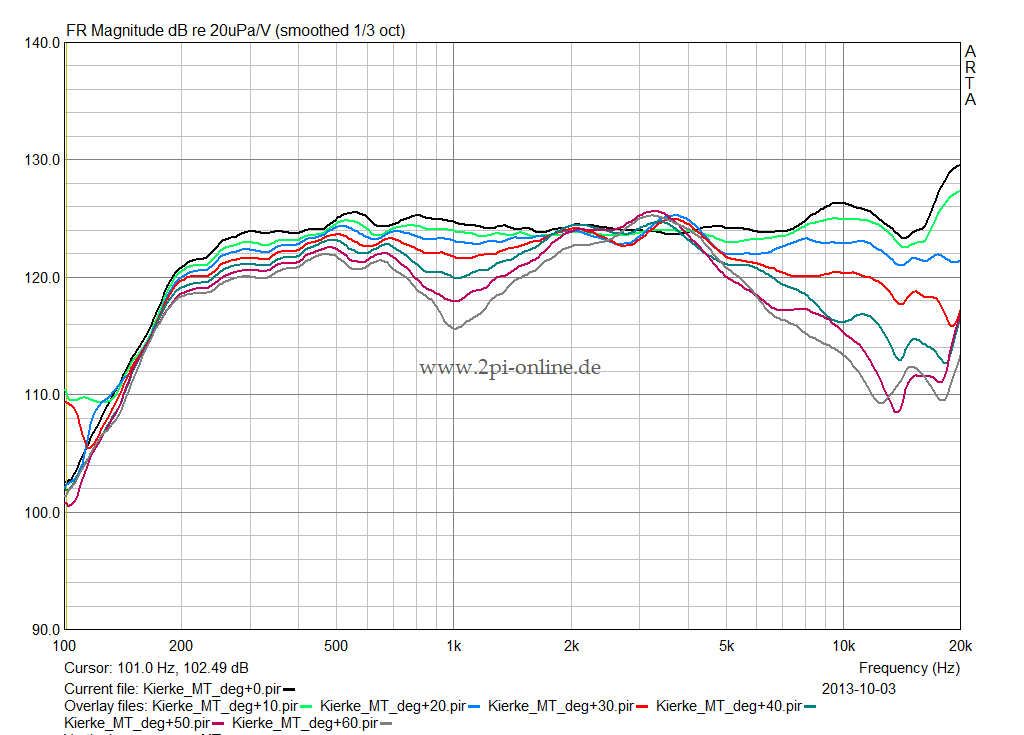
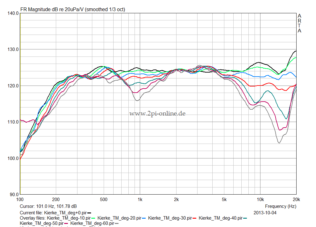
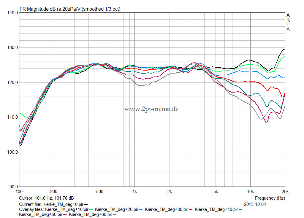
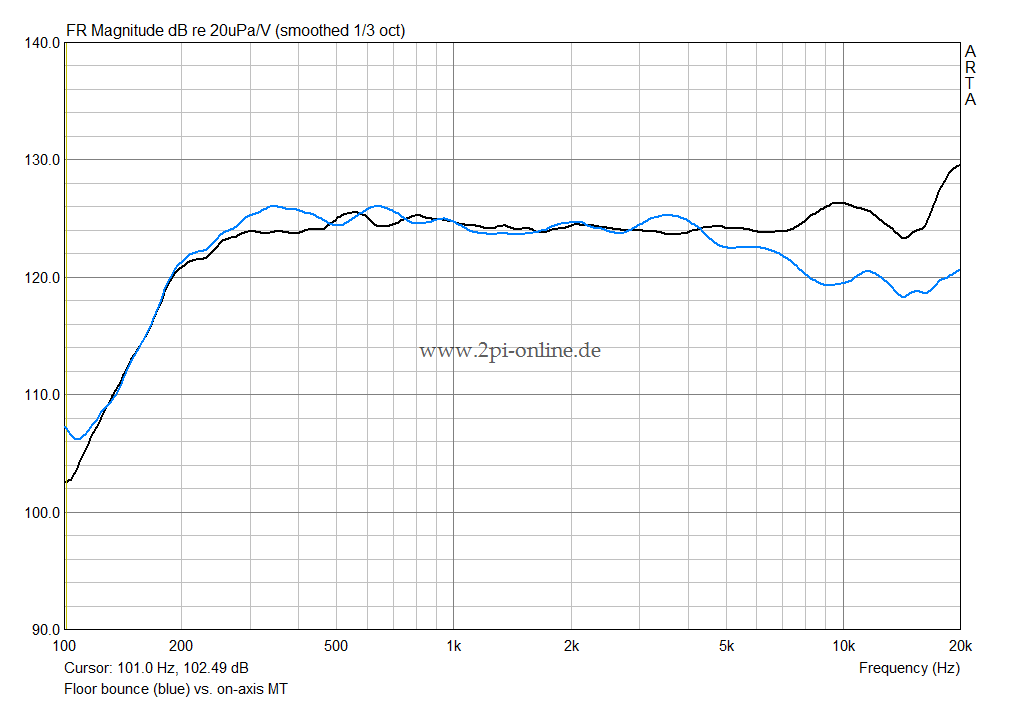
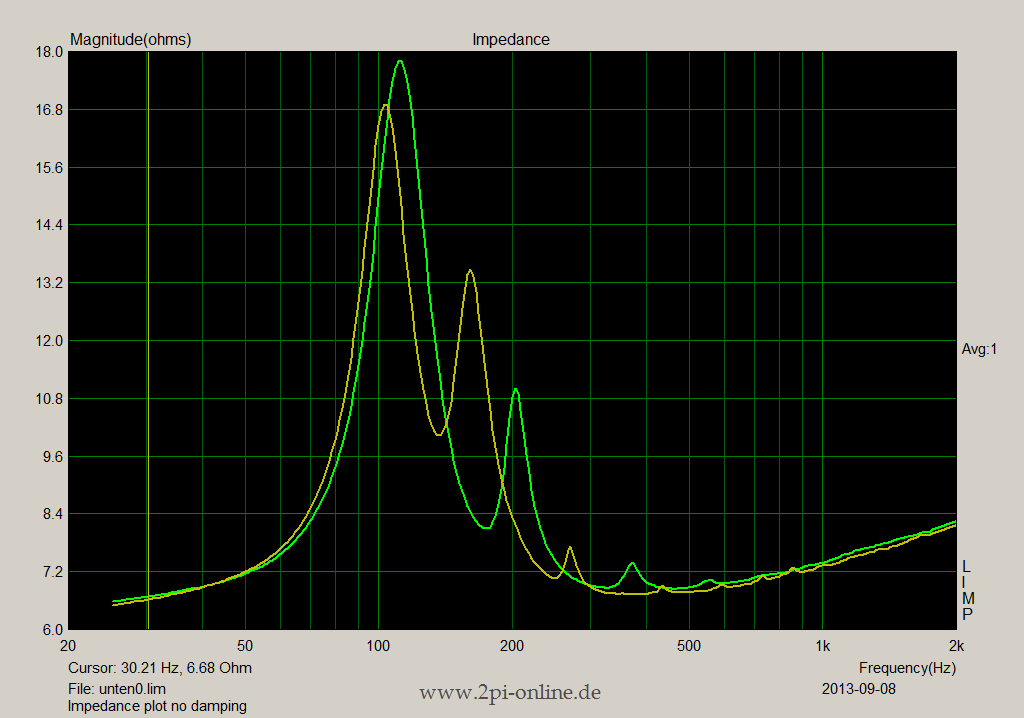
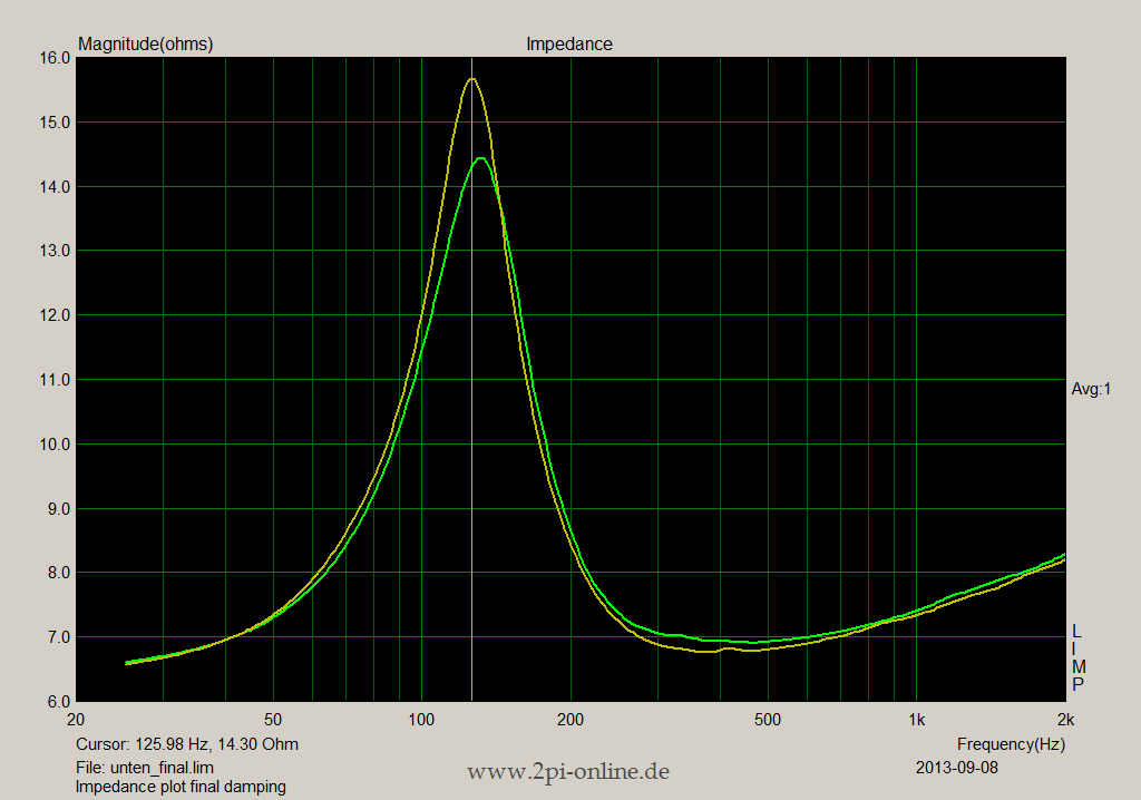
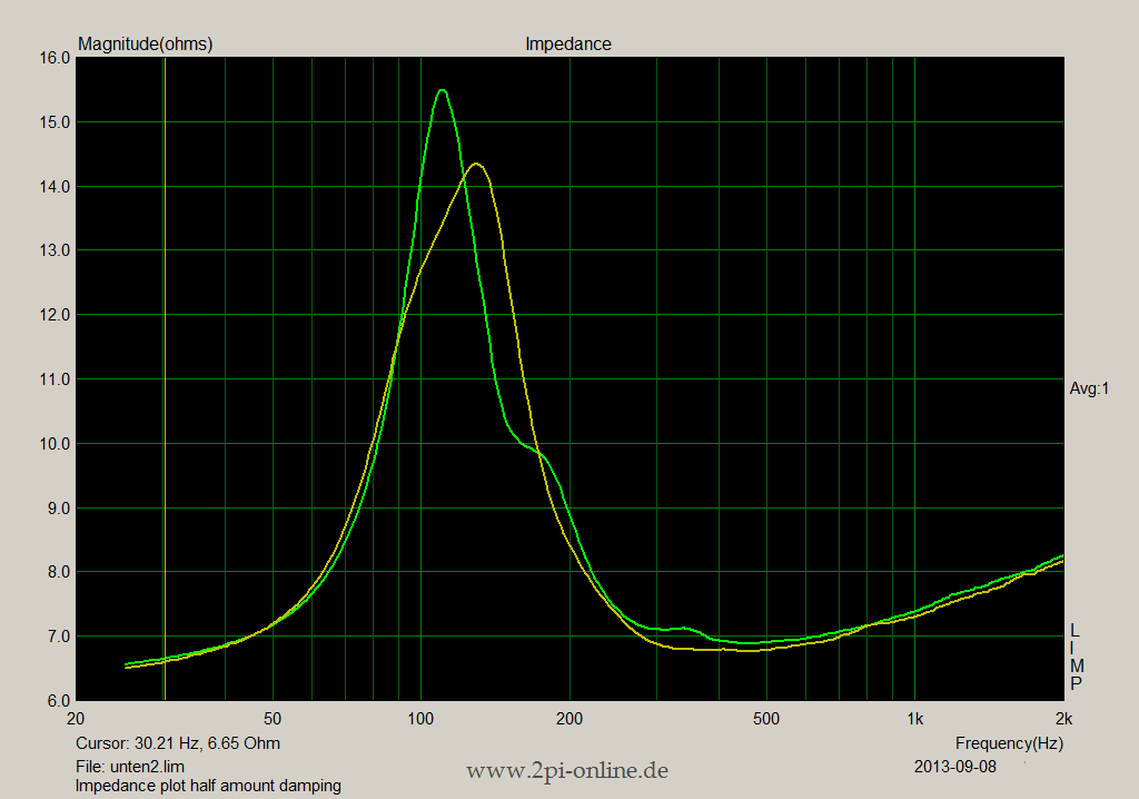
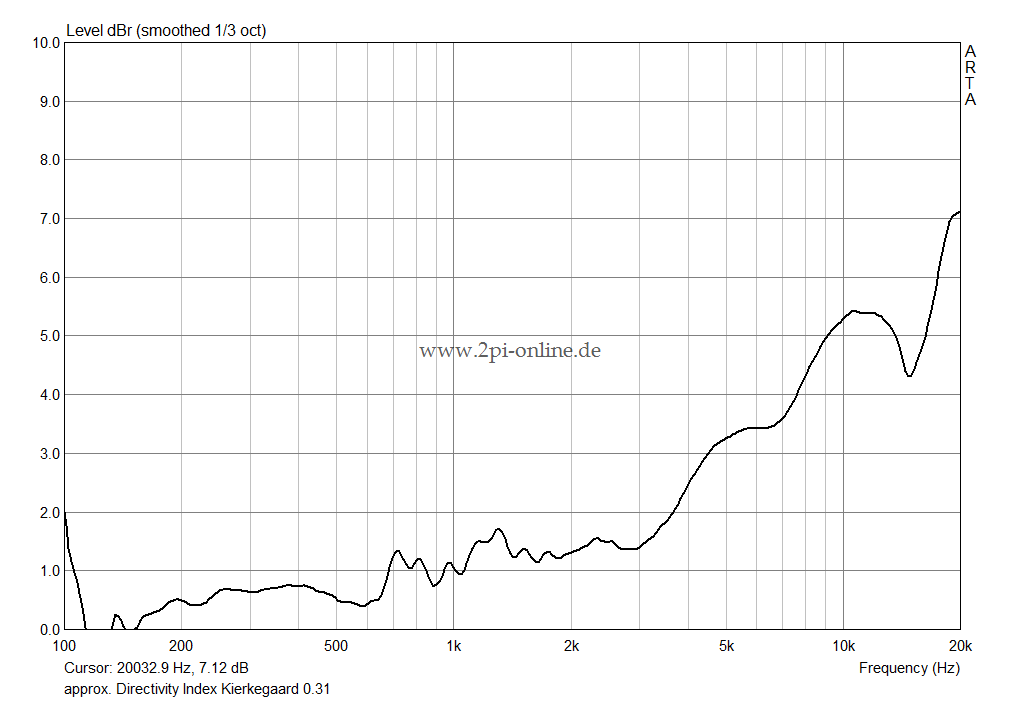
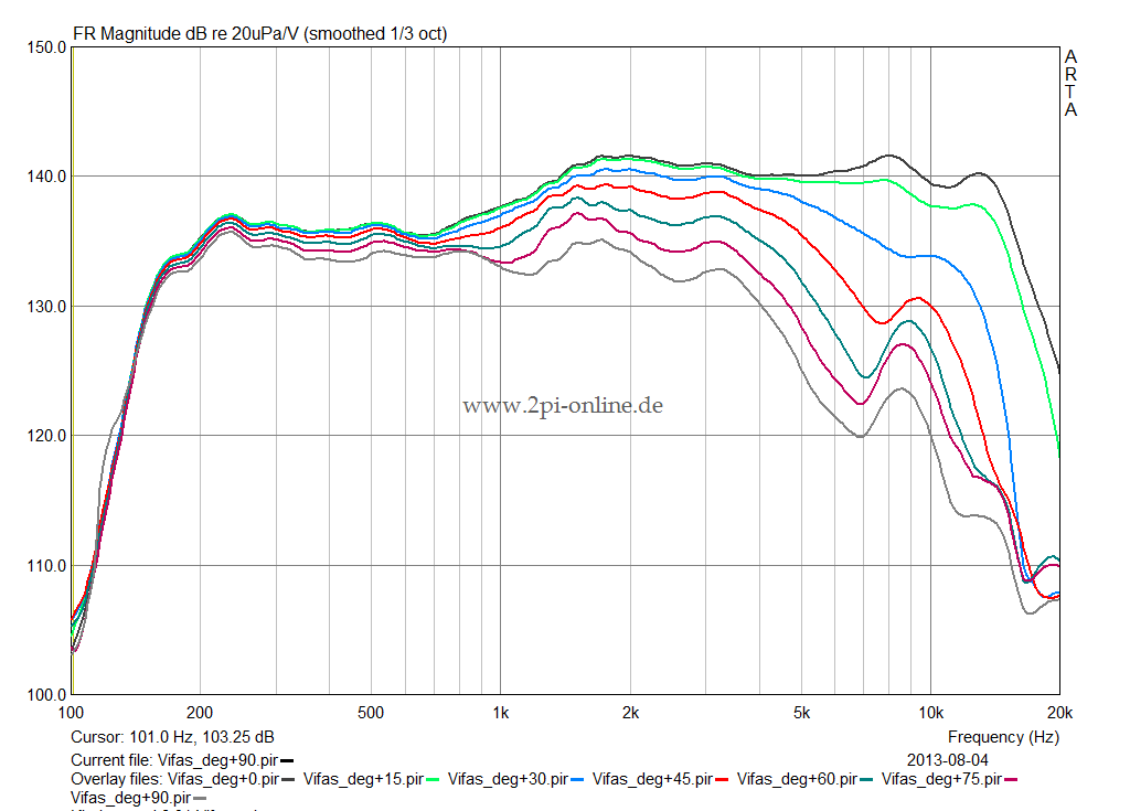
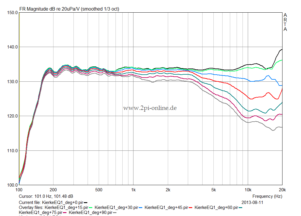
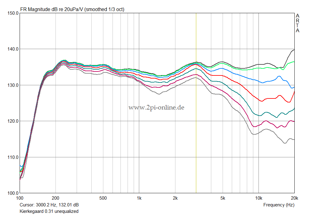
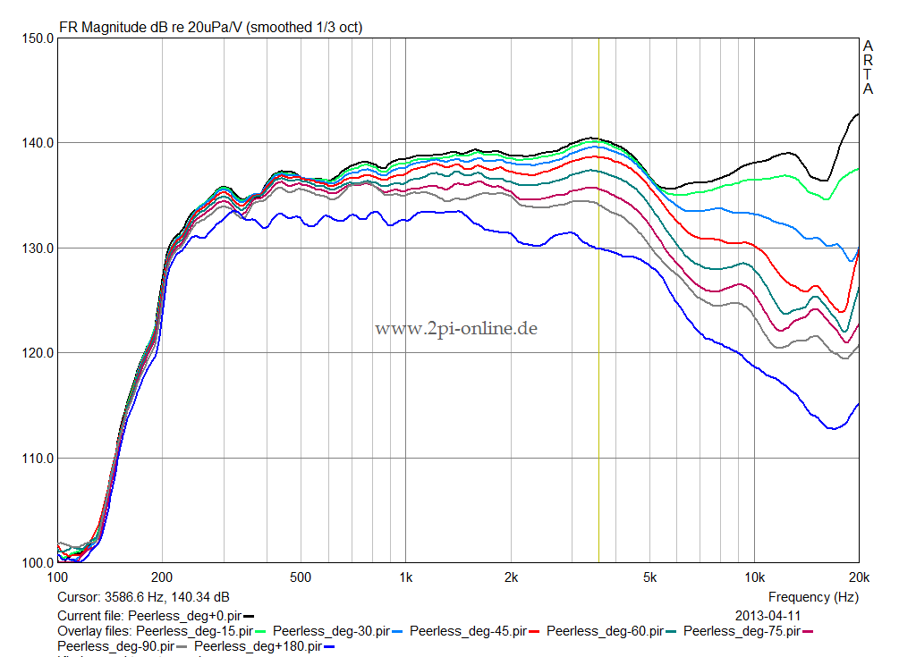
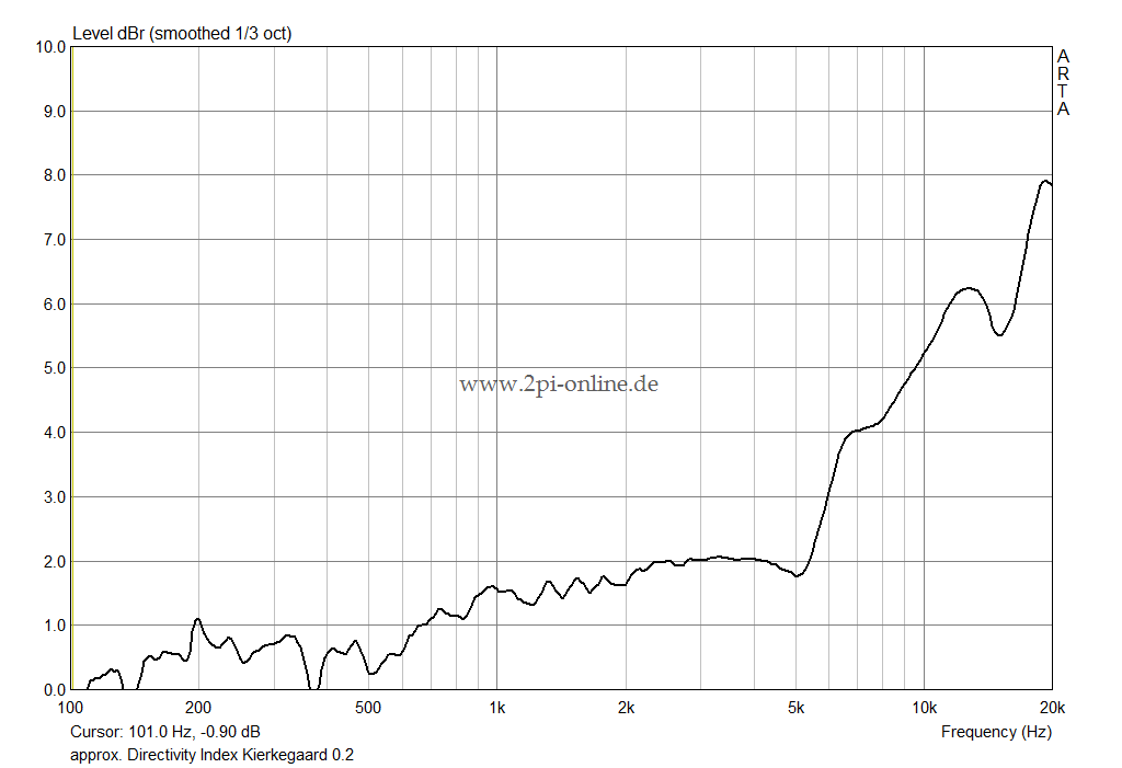
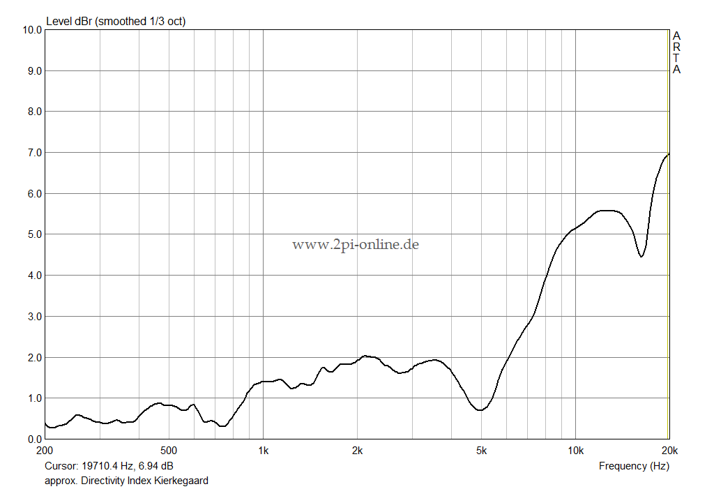
The successive approximation and the final result can be seen in the posted diagrams.
They start with the undamped resonances all the way to the correct amount of damping, which is right at the border of too much and too little.
The remaining issues between 300Hz and 450Hz are due to fact that the current damping material has already been worn out a little. They come and go with every measurement and are simply a sign of the critical damping at play. I am nearly convinced that fresh material will take care of it.

The green plot always represents the lower mid-woofer.

In this version, the tweeter inlet pipe is flanged to the front baffle and the tweeter is mounted to the baffle from the front. During the tests it was found that this link between the driver and the wood creates a resonance. The issue is described here.

In order to tackle the problem, I put a rubber o-ring between the tweeter and the baffle. My preference would have been a silicon ring with a Shore hardness of 70. But that was not available and so I took a material (Viton) with 75 temporarily. That already improved the situation considerably.

It remains to be seen what the final solution will be. The silicon ring has at least the potential to render the issue harmless.


Version 0.31 Horizontal Responses
Measurement Conditions:
- mic. distance 50cm
- tweeter 92cm above floor
- measured outdoors with periodic noise

This tweeter response looks much better now. There is virtually no diffraction at cabinet edges left.
What remains is the response shape caused by the baffle itself, which is a flat baffle step peaking at 3KHz and a subsequent peak at 5KHz.
But since all the response curves are now pretty parallel, it should be possible to equalize the remaining effects.

To the right, the raw response of the combined drivers is shown.
The used crossover is LR4 @900Hz.
Measurements from 0°...90° in 15° increments.


Below the first equalization attempt is visible.
The baffle step, which peaked around 3KHz is virtually gone. A remainder of a resonance at 650Hz needs more careful stuffing, though.

What will happen to the small bump around 10KHz and the overall response needs to be decided during listening tests once the 2nd speaker has been finished.

The total width of the housing has been increased by a few mm in order to have more space inside for internal chamfers for the Vifa mid woofers. But the baffle step can still be circumvented for those drivers.


Version 0.2:

In version 0.2 chamfers have been added as is visible on the picture of the prototype housing.

Measurement conditions:
Same as for version 0.1

The cabinet edges now re-radiate less energy, which is clearly visible in the FR diagram as well as in the approximated directivity index curve. However, the response is still below expectations and further changes on the housing will be required that make the design much more similar to version 0.3 on the project main page.

To the left the FR response of the two Vifa “woofers” is shown (measured at tweeter hight). In general also they exhibit a very uniform off-axis behavior up to 4KHz in this application.

As planned, the baffle step starts to form just below 1KHz.


Version 0.1:

The following diagrams describe version 0.1 of Kierkegaard, which corresponds to the sketches on the project main page. The baffle had rectangular edges without chamfers.

Measurement conditions:
- mic. distance 50cm
- tweeter 92cm above floor
- measured indoors with periodic noise

The tweeter does not beam enough to not illuminate the edges of the cabinet. Around 5KHz the response widens due to re-radiation off the sharp corners. The generally good behavior of the tweeter response is preserved even at 180°, which is represented by the dark blue response plot.

The anticipated waveguide effect of the front baffle is visible. However, with ~0.5dB between 500Hz and 2KHz in the estimated DI, the effect is very small. So I rather concentrate on getting the horizontal behavior as uniform as possible.

Last updated 03-Feb-2019